• Welcome to H4O! For a reduced ad experience, please login or register with the forum.

THORparts SAS #2 project...

4speedfunk

Well-Known Member
Messages
4,250
Location
Tardville
I'm hooked on the Airbag/Daystar combo. Even though I haven't tried it out yet...I can tell its going to work great. It fills a void between a passive bump stop, and an add-a-leaf. I'm familiar with air bumps but never used them. I'm pretty sure an air bump is not made to drive around on and support the weight of the truck...its only made to absorb a hit. And I think that's the big difference. This Airbag/Daystar combo is sort of like an air bump...but it also allows you to adjust for cargo, trailers, and the notorious saggy butt that all H3's eventually get. The airbags are totally capable of supporting the truck. They have a big 6" diameter footprint and they are made to carry the weight. Best of all...with the Daystar cradles, the airbag essentially disconnects and doesn't limit the droop. Nor do you have to worry about over stretching and possibly ripping a bag (hah-hah...he said "bag").

As for the "clapping"? I suppose that's possible on a high-speed whoop or something but, I was thinking more about 5 mph and under crawling. The bag doesn't come off the cradle unless you are close to max-droop. And God forbid you are going fast when you hit max-droop in this thing. "Clapping" sounds will be the least of your worries! You'll be spitting-out teeth and possibly your tongue, (and that's if you somehow kept it upright).
 

06 H3

a.k.a. "The Jackal"
Messages
9,506
Location
Meridian, ID
To reduce lift. I'm running those ruffstuff hangers and saw a T with stock hangers and stock springs sprung over and he had about 3in more lift then myself. Those hangers are huge!!!! They are also a hang up on the trail. These aren't
 

4speedfunk

Well-Known Member
Messages
4,250
Location
Tardville
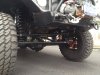
It would be awesome to keep the stock hangers when doing the SOA...it would save a ton of headaches! But, the SOA by itself nets you about 7.5" of lift...way too much. So they gotta be chopped off and replaced with smaller ones. That's the only reason. This will cut the total lift down to around 5.0". There are pictures on the net of a Colorado with a SOA, and the guy simply re-drilled new holes and moved the spring eye higher up, then trimmed the bottoms of the stock hangers. I suppose that could be done but, it almost sounds like more work. Plus, the new hangers are 1/4" formed pieces (from RuffStuff) and much beefier than the stock sheet metal buckets.
 

4speedfunk

Well-Known Member
Messages
4,250
Location
Tardville
Finishing touches:

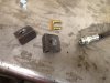
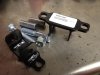
I tore apart the front suspension to prepare it for final assembly. There is some minor welding to do, and also a bunch of wire brushing and painting. First task is to make some brake line tabs. I know you can buy these but, I didn't want to pay $1.99 for them plus $18.00 shipping from California....so I just grabbed a piece of scrap angle and made my own.
attachment.php


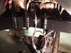
I chose to weld these to the frame rails, behind the where the coil spring will sit. This should offer some protection against getting "hooked" on trail debris. Next I installed new, longer brake lines, and re-shaped the factory rigid lines to fit the new tab location.
attachment.php


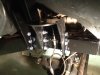
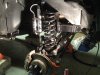
Finally, after everything got painted, I bolted the new shock-towers and coil buckets in place for good.
attachment.php


After this I re-installed the coil springs, and started working on the bump stops.
 

Attachments

  • brake 1.JPG
    brake 1.JPG
    116.5 KB · Views: 1,082
  • brake 2.JPG
    brake 2.JPG
    116.6 KB · Views: 1,035
  • brake 3.JPG
    brake 3.JPG
    112.3 KB · Views: 1,082

4speedfunk

Well-Known Member
Messages
4,250
Location
Tardville
Bump stops:

This is one topic that deserves some attention. There are many ways to skin this cat but, I like to re-use the original rear bumps on the front. These are progressive bumps and I like how they work on my truck, so I thought I would use them again on this one.

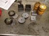
Normally, I would cut the "cups" off the rear frame rails but, the owner of this truck had previously cut them off when he added air-bags...so the cups were long gone. He did have the yellow foam core bumps, and that was good. So the first thing was to make some new cups. I did this by using some 3.25" thin-wall tubing (from a driveshaft) and some 3.25" bar stock. I cut a couple slivers of bar stock and turned a shoulder on them. I also bored a hole in the center. These get welded up to create the cups. The factory cups have four "dimples" cut into them that retain the yellow bumps...but I am going to use three small screws to accomplish the same thing. The cup pieces are shown in the lower left.

I also cut some square towers from tube stock to weld to the frame. These get a cap on the bottom, with a tapped hole. The two discs you see are 1" spacers, to "tune" the bumps....and I may or may not use these. The idea is that the cups get a single bolt in the center to hold them to the towers, then the bump gets installed over the bolt. I had to cut a recess in the backside center of the bumps for the bolt head...and you can see that in the upper right. The cups can be un-bolted from the towers, and spacers (such as fender washers) can be added to adjust the free space between the bumps and the landing pads on the axle. I'll get some more pics after everything is installed. Its much easier to understand after its all put together.
attachment.php
 

Attachments

  • bumps-1.JPG
    bumps-1.JPG
    117.6 KB · Views: 1,052

4speedfunk

Well-Known Member
Messages
4,250
Location
Tardville
Steering shaft:

One thing that a lot of people ask me is "whats up with the steering box?". I use a Nissan Delphi box from a Gen I (99-04) Xterra. This is an outboard mounted box and it fits the H3 like a glove. However, it has rather odd-ball splines on both the sector shaft and input shaft...that makes it sort of difficult to adapt.

On my first build, I found that the stock Hummer intermediate steering shaft will plug right onto the Nissan box with very little mods. I basically ground the splines off the input shaft, and reduced its diameter to match the input shaft of the stock rack & pinion. Then ground flats on it....a groove for the pinch bolt...and Ta-Dah! This works well and I have done two of these, (Squeaky runs this rig too)....and I'm not totally dismissing it as a cheap, quick solution. HOWEVER, once you do this...you are permanently modifying the input shaft of the box, and that means that if you have to swap in a new box in the future...you'll have to repeat this red-neck mod to bolt it up. The other important thing about doing this is that you must get the steering wheel and pitman arm perfectly aligned to center, because once you grind the flats...that sets the position of the steering wheel. Any adjustment you need to make will be done via the drag-link. H3's must have the steering wheel centered or you will get Stabilitrac errors.

On this truck...the owner had previously installed a body lift, and that was making the "grind and clamp" method difficult because the H3 intermediate shaft was already telescoped to its maximum length. So it was a perfect opportunity for me to come up with a better way to adapt the Nissan box to the H3 steering wheel. And here it is:

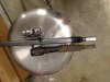
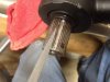
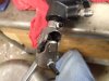
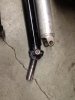
I spoke with Borgeson (a leader in steering shaft parts) and together we deduced that the Nissan box uses an 11/16"-36 spline input. So I ordered a u-joint to fit it, and specified a 1" DD female hole on the other end of it. Then I bought one of there generic telescoping shafts...this was a 3/4"DD male on one end and a 1"DD male on the other. It was way too long but, I can cut it down to fit. The 3/4" DD is the same size as the upper end of the stock H3 shaft and here's a pic showing the stock shaft and my new parts (Borgeson #450024 and #015225)...
attachment.php


Here is a close-up of the Borgeson u-joint splines...the same spacing throughout the ID...
attachment.php


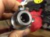
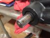
Now here is a shot of the Nissan input shaft. It has matching splines except for the "master" spline. This is a double-wide spline put here to index the steering wheel to "center" on a Nissan. The U-joint has no such master spline, and this needs to be removed. Another side benefit of doing this is that the u-joint can then be rotated one spline at a time until the steering wheel is properly centered...a must with the H3. You don't always have enough adjustment in the drag-link, so this makes a nice back-up if you need more...
attachment.php


Start by grinding the fat tooth away. Take your time and don't get into the splines on each side that you are trying to keep...
attachment.php


Once you get most of the tooth ground off...take a V-shaped jeweler's file and cut a groove down the middle of the fat spline. The idea is to mimic the spline spacing that you see on the rest of the shaft. This takes a steady hand...
attachment.php


When done it looks like this...
attachment.php


I also took a few minutes to dress some of the other splines that had some burrs on them. The new joint now fits perfectly, and it can be indexed to any position...
attachment.php


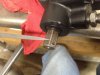
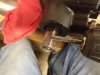
The rest of the steering shaft install consists of shortening the Borgeson telescoping shaft, and hooking it all up. I'll post some pics after I get it all in place.
 

Attachments

  • steering 01.JPG
    steering 01.JPG
    67.8 KB · Views: 1,052
  • steering 2.JPG
    steering 2.JPG
    94.6 KB · Views: 1,015
  • steering 3.JPG
    steering 3.JPG
    125.4 KB · Views: 1,063
  • steering 4.JPG
    steering 4.JPG
    126.8 KB · Views: 1,017
  • steering 5.JPG
    steering 5.JPG
    118.9 KB · Views: 1,040
  • steering 6.JPG
    steering 6.JPG
    117.2 KB · Views: 1,073
  • steering 7.JPG
    steering 7.JPG
    99 KB · Views: 1,055

4speedfunk

Well-Known Member
Messages
4,250
Location
Tardville
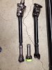
The other day I got the driveshafts done and installed. The rear needed to be 1.75" longer and like all late-model driveshafts...its easier to just make a new one (from SAE steel tubing instead of weird aluminum size). The yoke had been previously pulled out for the Rancho lift and then even more for the SOA, so it was needed. New Spicer joints were installed and the yoke got a fresh polish too...
attachment.php
attachment.php


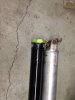
The front driveshaft was a THORparts unit that I built a few years ago. It had recently been freshened up by the owner and all it needed was a longer slip yoke. So I swapped the 7" for an 8.5" and called it done. This shaft was based on the GM/Dodge 3R Cardan-CV and it uses a casting that is made specifically for the H3's transfer-case flange. That casting is getting scarce, and frankly I've never been impressed by the 3R CV. It is shown below (top). Below it is the new longer slip collar which simply pushes-on. On the bottom is my latest version of the front driveshaft. This one uses a Ford 1310 Cardan-CV and it has much less spring tension in it...makes for a smoother drive. However, since there is no way to bolt it up to the H3 t-case flange, I also made the thin adapter that mates the H3 flange to the Ford casting. The flange you see on the end of it is actually an output flange from a 3394 H3 t-case, and the shiny piece is the adapter.
attachment.php


Squeaky is currently running one of these (in conjunction with his AAA tow-truck membership), and so am I. I'll probably crank a few adapters out and sell them if anyone is interested. The shaft can be bought from any driveline shop...all standard stuff.
 

Attachments

  • IMG_0677.jpg
    IMG_0677.jpg
    163.1 KB · Views: 976
  • IMG_0678.jpg
    IMG_0678.jpg
    142.5 KB · Views: 1,034
  • IMG_0676.jpg
    IMG_0676.jpg
    181 KB · Views: 1,038

4speedfunk

Well-Known Member
Messages
4,250
Location
Tardville
Next came shocks. I was really torn on this build....10" or 12"? I decided on the 10"s because I anticipate lowering this truck, and its sitting pretty high right now. So, the 10"s showed up and I quickly realized that they are very short and don't allow for much droop. But...like I said this thing is sitting very high. The main reason for the extra height is the high-pinion pumpkin. Its quite close to the exhaust manifold, so I wanted to start off high and then gradually adjust it lower. The key is to find the sweet spot between up-travel, bump-stop location, and static ride height. I actually think the low-pinion fits the H3 (at least the 5-cyl version) better but, the high-pinion is stronger.

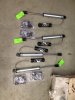
The shocks were custom valved by Down South Motorsports. They seem a tad stiff but, its hard to tell if its the springs/air-bags...or the shocks themselves. I got all (4) the same...Fox #980-02-032...
attachment.php


Rather than fart around with pin-bars...I decided to try some pin-bar eliminators on the rear. These came from Rough Country and I'm not overly impressed with them. Now I get to fart around with the eliminators! The hole spacing was for Jeep shocks of course, so I had to open them up into slots to fit the GM hole spacing. 30 seconds with a die-grinder did the trick. Once I got them in place I realized that the cross bolts could not be inserted. So the eliminators would need to be installed on the shock first...so it really was a big freakin hassle for nothing. The only thing these allowed me to do was to use a standard eye-to-eye shock...
attachment.php
attachment.php


Once installed it all looks like this...
attachment.php
 

Attachments

  • IMG_0682.jpg
    IMG_0682.jpg
    169.3 KB · Views: 975
  • IMG_0679.jpg
    IMG_0679.jpg
    227 KB · Views: 948
  • IMG_0680.jpg
    IMG_0680.jpg
    139.7 KB · Views: 949
  • IMG_0684.jpg
    IMG_0684.jpg
    273.7 KB · Views: 1,080

4speedfunk

Well-Known Member
Messages
4,250
Location
Tardville
ITS ALIVE!!!!

Did the first test drive today. To my amazement...she fired up from her two-month slumber without too much trouble. I had a PS hose leak...sprayed fluid everywhere...but ZERO traction control, Stabilitrac, Brake, 4-wheel system, or ABS lights. Absolutely NONE! Turned the key and put it in gear...drove right out. This completely stunned me...I thought for sure I would have something lit-up. Nope.

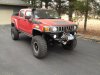
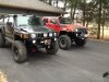
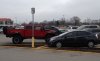
As you can see...this thing is insane-looking. It dwarfs my SASH3 when I parked next to it. It missed my shop door by less than a half-inch, and I had to clamp the door all the way open with vise-grips to get enough room to clear it. I really had this truck torn apart, and that first drive is quite nerve-racking. So I took it slow...cruzed into the small town I live in. Man did I get the looks!...you are truly a rock-star when driving this. Overall it went very well. I have a few things to sort out...but nothing electronic. It needs an alignment of course, and I feel the ride-height and spring stiffness are both too much. I'll be looking into making some adjustments in those areas. I stopped at the local Rural King to get some more PS fluid...couldn't resist parking next to a Prius!

attachment.php
attachment.php
attachment.php
attachment.php
attachment.php
attachment.php


I'm going to take a couple days to clean up my shop, and put some more miles on the T. Then I will pull it back in for some adjustments and I also need to hook up the ram assist.
 

Attachments

  • IMG_0685.jpg
    IMG_0685.jpg
    284.4 KB · Views: 939
  • IMG_0686.jpg
    IMG_0686.jpg
    264.8 KB · Views: 940
  • IMG_0687.jpg
    IMG_0687.jpg
    331.7 KB · Views: 972
  • IMG_0688.jpg
    IMG_0688.jpg
    276.1 KB · Views: 967
  • IMG_0691.jpg
    IMG_0691.jpg
    328.9 KB · Views: 965
  • IMG_0689.jpg
    IMG_0689.jpg
    596 KB · Views: 938
Last edited:
Top